

For over 25 years, Tec-Ease has developed GD&T Tips to help users clearly understand the terms, symbols, and concepts defined in the ASME Y14.5 Standard. These concise, easy-to-digest resources focus on the correct application of GD&T, reinforcing not just what the symbols mean—but how they function in real-world design, manufacturing, and inspection.
Each Tip is rooted in the Standard itself, with references spanning the 1994, 2009, and 2018 versions, making them valuable for teams working across multiple revisions. Whether used as quick refreshers, training reinforcements, or on-the-job references, GD&T Tips are a practical way to build confidence and consistency in applying GD&T correctly.
In addition, select Tips address related ASME Standards, including Y14.8 and Y14.41, providing broader context for model-based definition and digital product definition practices. Each Tip is short, focused, and easy to consume, making them ideal for reinforcing learning or quickly clarifying a specific GD&T question. Many Tips also include a brief video to further illustrate the concept and enhance understanding.
Several Tips are available for free on the Tec-Ease.com Website. All Tips are available within the GD&T Reference Center. You can also sign up for our email list to receive any new or updated Tips right in your inbox, at no cost.
Sample GD&T Tip
Simultaneous Requirements with Composite Feature Control Frames
Watch Tip Video
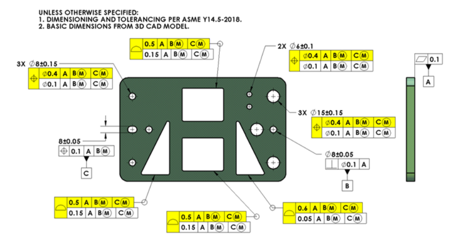
When two or more position or profile tolerances reference the same datum features, in the same order, and with the same modifiers, those features form a pattern that must be inspected simultaneously—unless a separate note says otherwise. Easy enough. This would be the case for the upper segment of all seven of the composite position or profile tolerances shown here.
The upper segment of a composite feature control frame locates and orients each feature in the pattern relative to the datum reference frame, just like a normal position or profile of a surface tolerance would control each feature. Things are different for the lower segment of each composite feature control frame though. The datum features referenced in a lower segment constrain only rotational degrees of freedom. So, a lower segment refines feature-to-feature location, possibly the form of each feature (if it’s a composite profile tolerance), and the orientation of the pattern of features, but it doesn’t control location relative to the datum reference frame
Here’s the twist: even if multiple composite feature control frame lower segments list the same datum features in the same order, with the same modifiers, the features controlled by those lower segments are not automatically linked. The pattern created by each lower segment stands alone, with each creating its own Feature-Relating-Tolerance-Zone-Framework (FRTZF).
Suppose you have seven composite feature control frames on a drawing, like the one shown above. That means seven separate lower-segment groups. If some of those features need to be combined into a larger pattern—say, when that larger group mates with another part all at once — you must tell the inspector by adding one or more SIM REQT notes.
As shown in the drawing below, placing SIM REQT #1 beneath the applicable feature control frames tells everyone those lower segments form one group to be inspected together, as a larger pattern. What began as seven groups might now become five in the drawing below. Additional notes, like SIM REQT #2 or #3, can define other groups of features that each form a larger pattern, as needed to meet the functional requirements of the part. So, for the drawing shown below, there are three FRTZFs, instead of seven.
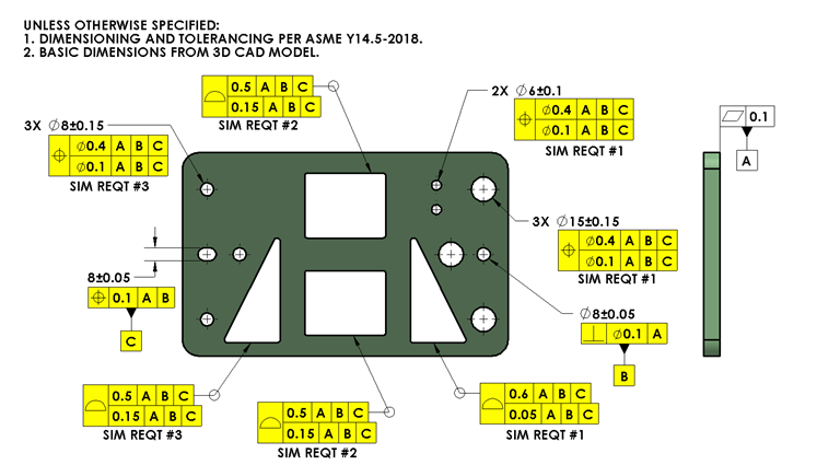
Remember, the datum feature references in the lower segment constrain only rotational degrees of freedom — no translations. So, the lower segment refines feature-to-feature location, possibly form (if a composite profile tolerance), and pattern orientation, not location to the datum reference frame.
So don’t assume that similar looking composite lower segments share simultaneous requirements. If you want them to be grouped, you must say so—with a SIM REQT note.
In accordance with ASME Y14.5M-1994, ASME Y14.5-2009 & ASME Y14.5-2018
GD&T Resources by Tec-Ease